Replacing a failed rooftop air conditioner on a travel trailer or fifth wheel is one of those jobs that sounds terrifying until you break down the mechanical sequence. I have swapped out well over sixty rooftop units across every roof substrate imaginable — rubber EPDM, fiberglass, and TPO membrane. The entire system is held to your camper by exactly four long steel bolts and a compressed closed-cell gasket. There is zero structural glue holding the unit down, and in ninety percent of replacement scenarios, you do not even need to cut a single wire if your replacement unit matches the ceiling distribution box.
The real challenge is not the electrical circuitry. The challenge is safely maneuvering an 85-pound to 105-pound compressor housing onto a rubber roof without puncturing the membrane, ensuring the structural framing around the standard 14” × 14” roof opening is bone-dry, and torquing the mounting bolts to the exact specification required to stop rainwater leaks without crushing the gasket.
Essential Tools and Materials Checklist
Before climbing onto your RV roof, gather the exact tools needed for the teardown and installation. Trying to scramble down an extension ladder because you are missing a 3/8” socket or wire nuts leads to damaged roof decking.
| Tool / Material | Recommended Specification | Purpose |
|---|---|---|
| New Rooftop AC Unit | 13,500 BTU or 15,000 BTU 120V AC | Direct replacement unit |
| Closed-Cell Neoprene Gasket | 14” × 14” square (typically 3/4” to 1” thick) | Primary perimeter water seal |
| Leveling Shims / Foam Pads | High-density EVA foam strips | Evens out roof crown slope |
| Socket Set & Ratchet | 3/8” drive with 3/8” and 7/16” deep sockets | Tightening corner mounting bolts |
| Torque Wrench | Inch-pound range (0 to 100 in-lb) | Precision bolt torque (40–50 in-lb) |
| Utility Knife & Scraper | Plastic putty knife and fresh razor blades | Removing old sealant without tearing TPO/EPDM |
| Lap Sealant | Dicor® 501LSW Self-Leveling Lap Sealant | Sealing legacy screw penetrations |
| Mineral Spirits / Denatured Alcohol | Solvent cleaner | Degreasing roof membrane around opening |
| Wire Strippers & Lineman Pliers | 10–14 AWG rating | Splicing 120V AC Romex leads |
| Digital Multimeter | CAT III 600V rated | Verifying circuit de-energization |
Critical Safety Rule: Never apply silicone caulk or self-leveling lap sealant directly underneath the 14” × 14” perimeter foam gasket. Rooftop RV air conditioners rely exclusively on dry mechanical compression of the closed-cell foam against the clean roof membrane. Smearing silicone or goop under the gasket prevents uniform compression and virtually guarantees a persistent roof leak within 12 to 18 months.
Pre-Installation Electrical Safety Verification
Before touching a single screw on the ceiling assembly inside your RV, you must physically kill power at two distinct sources. RV HVAC systems operate on high-voltage 120V AC for the hermetic compressor and dual-shaft fan motor, combined with low-voltage 12V DC control signals from the wall thermostat.
- Disconnect Shore Power: Unplug your 30A or 50A RV power cord from the campsite pedestal or household receptacle.
- Shut Down Inverter / Generator: If your coach is equipped with an auto-start generator or whole-coach inverter system, switch the inverter control panel completely off and lock out the generator breaker.
- Trip the Air Conditioner Breaker: Open your RV power distribution center and flip the dedicated 20A AC branch circuit breaker to the “OFF” position.
- Disconnect 12V House Batteries: Disconnect the negative terminal of your house battery bank to ensure the 12V DC thermostat control circuit cannot energize the relay box while your fingers are inside the junction box.
- Verify Zero Voltage with a Multimeter: Remove the ceiling grille, unscrew the metal electrical junction cover, and probe between hot (black), neutral (white), and equipment ground (bare copper/green) using your digital multimeter set to AC volts. The display must read 0.0 V before proceeding.
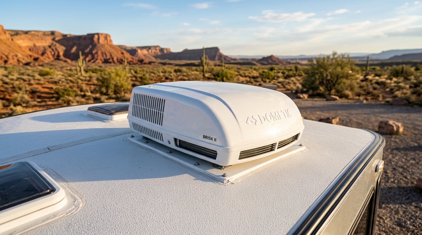
If you are replacing an older non-ducted unit with a modern high-efficiency model like the Dometic® Brisk II Rooftop Unit, verify whether your existing ceiling assembly (ADB) is compatible or if you need the matching interior plenum kit. For an in-depth teardown of modern rooftop units, refer to our Dometic Brisk II RV air conditioner review.
Removing the Old Rooftop Air Conditioner
Step 1: Remove Interior Ceiling Grille and Control Box
Working inside the camper, pop off the cosmetic plastic filter grilles. Remove the four to six Phillips sheet metal screws securing the outer ceiling shroud. Lower the shroud down and set it aside.
Inside the plenum, you will see a stamped steel mounting frame held in place by four long hex-head corner bolts extending up into the rooftop pan. Disconnect the 120V AC supply Romex wire nuts (black to black, white to white, green to ground) and loosen the Romex cable clamp. Disconnect the multi-pin umbilical harness connecting the ceiling box to the rooftop condenser.
Step 2: Remove the Four Mounting Bolts
Using a 3/8” or 7/16” socket, unbolt the four corner tie-down bolts. Support the steel mounting frame as you loosen the final two bolts. Lower the metal frame and the return air divider down. You can now see straight up through the 14” × 14” square roof cutout to the sky.
Step 3: Break the Old Gasket Seal on the Roof
Climb onto the RV roof using a secure ladder. Pad the ladder contact rails with foam pipe insulation or microfiber towels where they rest against the camper sidewall to prevent gutter dents.
Remove the outer plastic shroud by extracting the perimeter screws. With the plastic shroud off, gently push against the lower metal base pan with your hands. Over 5 to 15 years of exposure, the old rubber gasket will have adhered slightly to the roof membrane. Do not pry aggressively with a steel screwdriver or pry bar, which will slice straight through EPDM rubber. Instead, use a steady, firm rolling push against the metal housing. The unit will pop loose from the roof decking.
Step 4: Safely Lowering the Old Unit
Never attempt to carry a 90-pound air conditioner down an extension ladder by yourself. The safest method for two people is to slide the old unit down an angled ramp formed by two 2×4 boards wrapped in moving blankets resting from the roof edge to the bed of a pickup truck. If working solo, dismantle the old unit on the roof: unbolt the fan motor and compressor shroud to lower the components down in manageable 25-pound segments.
Preparing the 14” × 14” Roof Opening
Once the roof surface is clear, inspect the wooden structural framing around the opening.
- Check for Moisture Damage: Probe the perimeter wood rafters with an awl. If water has leaked past the old gasket, the plywood decking and 1.5” spruce blocking may be rotted. Replace any decayed lumber and allow damp insulation to dry completely before installing the new unit.
- Verify Internal Blocking: The four vertical mounting bolts apply approximately 45 in-lb of clamping force. There must be solid wood blocking sandwiched between the roof decking and interior ceiling panel. If your factory framing has collapsed, slide custom cut 1” × 1.5” spruce blocks into the perimeter cavity to prevent the roof from bowing when bolts are torqued.
- Scrape and Clean the Surface: Use a plastic putty knife to scrape away residual foam gasket bits. Wipe down the entire 24” × 24” contact perimeter using clean rags soaked with denatured alcohol or mineral spirits until the membrane is pristine, oil-free, and bone-dry.
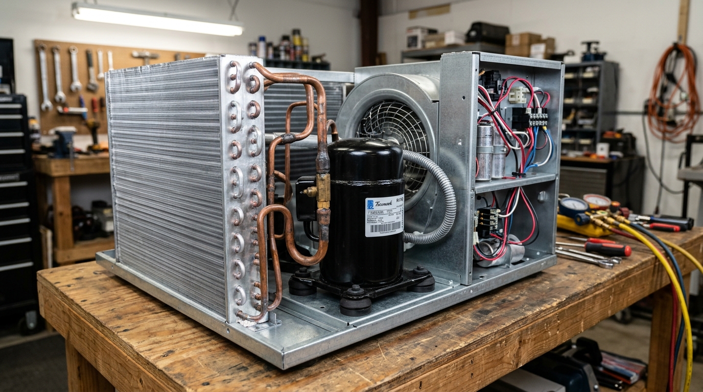
Installing the New Rooftop Unit
Step 1: Adhere the New Foam Gasket
Most replacement units arrive with the 14” × 14” closed-cell neoprene gasket pre-installed on the bottom of the stamped steel base pan. If your unit requires manual gasket installation, peel off the adhesive backing paper and press the gasket firmly to the perimeter of the base pan. Ensure the joint seam is positioned at the rear (condenser end) of the unit, never at the front where driving wind and highway rain could force moisture through the seam.
Step 2: Hoist and Position the New Unit
Hoist the new air conditioner onto the roof. Slide the unit carefully over the roof membrane — never drag sharp metal edges across the rubber. Position the base pan squarely over the 14” × 14” cutout. Have a helper inside the RV look up through the ceiling opening to guide you until the downward-projecting flanges of the base pan are centered evenly within the cutout on all four sides.
Step 3: Install the Return Air Divider
The vertical return air baffle separates the warm cabin return air from the cold discharge air. Measure the exact thickness of your RV roof sandwich (from interior ceiling drywall to exterior roof decking — typically between 2.5” and 4.5”). Trim the provided foil-faced insulating divider to height using a utility knife. Seal both vertical edges with UL 181-rated aluminum foil tape. If this divider leaks, cold supply air short-circuits straight back into the intake, freezing your evaporator coil solid within 30 minutes.
Step 4: Torque the Mounting Bolts to Specification
Position the stamped metal ceiling mounting bracket from inside the RV. Thread the four long steel corner bolts through the bracket and into the threaded speed nuts in the rooftop base pan.
Tighten the bolts by hand in an alternating crisscross pattern (front-left, rear-right, front-right, rear-left) to draw the rooftop unit down evenly.
Crucial Gasket Compression Metric: A new uncompressed gasket is approximately 1.00 inch thick (≈ 25.4 mm). Proper installation requires compressing the gasket down to exactly 50% of its relaxed thickness — roughly 0.50 inch (≈ 12.7 mm). Most modern brackets feature visual indicator tabs: tighten until the metal tabs firmly contact the ceiling substrate, or use an inch-pound torque wrench to tighten each bolt to 40 to 50 in-lb (4.5 to 5.6 N·m). Never over-tighten beyond 50 in-lb, or you will deform the base pan and crush the closed cells, causing the gasket to wick water.
Electrical Connections and Wiring Specifications
Connecting the electrical feeds is straightforward when following standardized color coding. Modern RV air conditioners segregate high-voltage power from low-voltage thermostat controls into two distinct wiring sections.
| Circuit Type | Wire Color / Terminal | Function | Connection Destination |
|---|---|---|---|
| 120V AC Power | Black (Hot) | 120V Line Feed | Connects to black lead on AC junction box |
| 120V AC Power | White (Neutral) | Return Neutral | Connects to white lead on AC junction box |
| 120V AC Power | Bare Copper / Green | Equipment Ground | Screws directly beneath chassis ground lug |
| 12V DC Control | Red / Pink (+12V) | Continuous 12V Supply | Powers thermostat control relay board |
| 12V DC Control | Black / Blue (Common) | 12V Return Ground | Common negative return to RV 12V bus |
| 12V DC Control | Yellow (Cool Call) | Compressor Trigger | Closes relay to start compressor circuit |
| 12V DC Control | Green (Fan High) | High-Speed Blower | Energizes high-speed blower motor winding |
| 12V DC Control | Brown (Fan Low) | Low-Speed Blower | Energizes low-speed blower motor winding |
| 12V DC Control | Blue / White (Heat) | Furnace or Heat Strip | Triggers LP furnace or electric heat element |
Inside the electrical junction box on the ceiling plenum:
- Pass the 120V AC Romex NM-B 12/2 cable through the metallic cable clamp and tighten the two clamp screws.
- Strip 5/8” of insulation from the black and white conductors.
- Twist the black hot wire to the AC control box black lead with a yellow wire nut, securing the connection with Scotch® Super 33+ electrical tape.
- Twist the white neutral wire to the control box white lead and cap with a wire nut.
- Secure the bare copper ground wire firmly beneath the green grounding screw on the stamped steel frame.
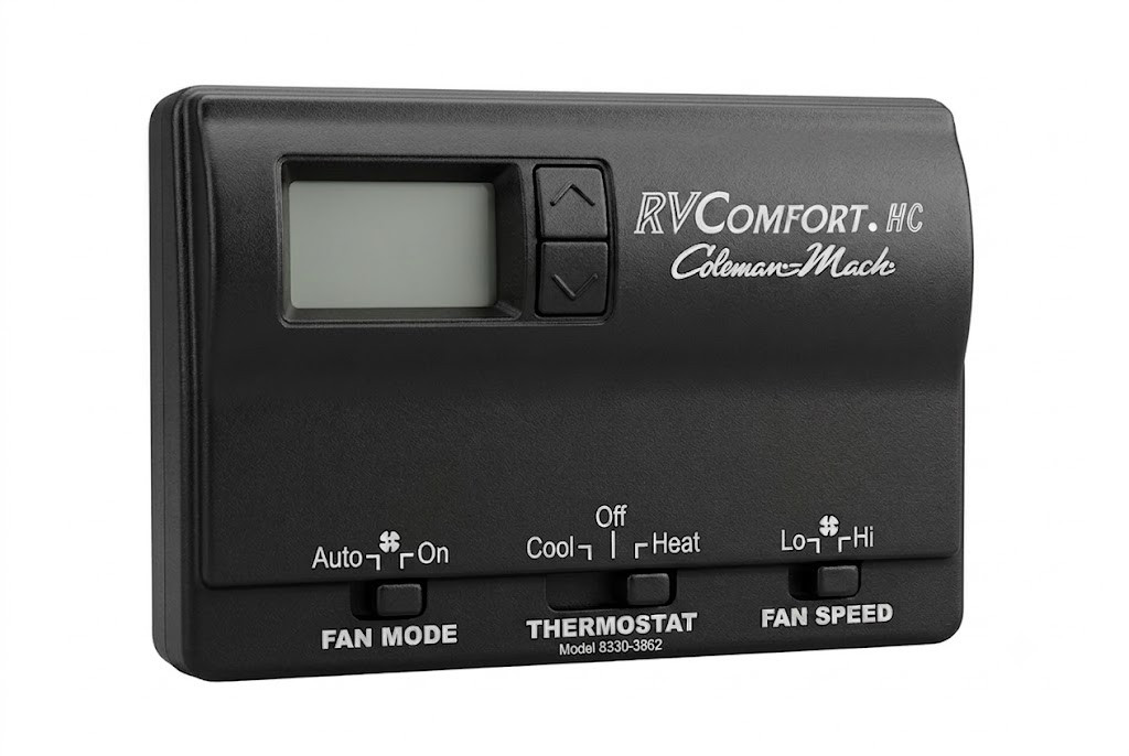
- Connect the low-voltage thermostat wire harness by plugging in the multi-pin connector or matching color-coded spade terminals. If you are upgrading your analog sliders to an LCD thermostat, consult our detailed RV AC thermostat replacement guide.
If you frequently run your rooftop unit from an inverter generator or off-grid solar setup, now is the ideal time to wire an advanced soft starter module directly into the rooftop compressor run capacitor. Read our testing findings on how a soft starter cuts starting amps by up to 70% in our soft starter for RV AC guide.
Final Operational Commissioning and Testing
Re-energize your 12V house battery disconnect and reset the 20A branch circuit breaker at the main breaker panel.
- Verify Fan Function: Set the wall thermostat to “FAN ON - LOW” and confirm the blower pushes air smoothly. Switch to “FAN ON - HIGH” and verify increased CFM airflow and zero mechanical vibration.
- Initiate Cooling Cycle: Lower the temperature setpoint 5°F below ambient room temperature. Listen for the thermostat relay click, followed by the compressor spinning up within 5 to 15 seconds.
- Measure Delta-T (Temperature Differential): Insert a digital probe thermometer into the return air intake grille and note the temperature (e.g., 82°F / 27.8°C). Place the thermometer probe directly into the cold air discharge louvers. After 15 minutes of continuous compressor run time, the discharge air should measure 16°F to 22°F (8.9°C to 12.2°C) colder than the intake. This confirmed delta-T proves proper refrigerant charge and sealed baffle airflow.
- Water Spray Leak Test: Have an assistant stand inside the RV watching the perimeter of the 14” × 14” ceiling opening while you gently run a garden hose on the RV roof uphill from the air conditioner shroud for 10 minutes. If the ceiling remains completely dry, reinstall the decorative plastic lower shroud and filters.
For a comprehensive comparison of the top-performing replacement units on the market today, see our updated benchmark review of the best RV air conditioner 2026 models.
Check current pricing and availability on complete RV rooftop replacement units on Amazon